Interim Report for Project Entitled:
Full Scale Wind Load Testing
of Aluminum Screen Enclosures
PO Number A95F33
Performance Period: 1/6/2014 – 6/30/2014
Submitted on
March 15, 2014
Presented to the
Florida Building
Commission
State of Florida
Department of Business and Professional Regulation
by
Forrest J. Masters,
Ph.D., P.E., masters@ce.ufl.edu, (352) 392-9537 x 1505, Principal Investigator
Sungmoon Jung, Ph.D.,
sjung2@fsu.edu, (850) 410-6386
Designated Project Leader: Forrest Masters
Engineering School
for Sustainable Infrastructure & Environment

Table of Contents
Table
of Contents
1. Applicable Sections of the Code....................................................................................................... 1
2. Executive Summary........................................................................................................................ 1
2.1. Description of Issues................................................................................................................. 1
2.2. Recommendations for the Code.................................................................................................. 1
3. Scope of Work................................................................................................................................ 1
4. Deliverables.................................................................................................................................... 1
5. Detailed Project Description............................................................................................................. 1
6. Reference / Project Material............................................................................................................. 3
7. Appendices.................................................................................................................................... 3
7.1. Appendix A – Letter from the Aluminum
Association of Florida...................................................... 4
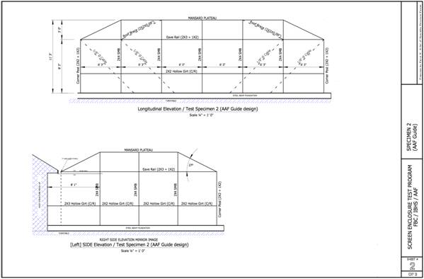
7.2. Appendix B – ‘AAF’ design plans and rendering of
structural model............................................... 7
7.3. Appendix C – Strain gauge locations........................................................................................... 9
·
1622.1.2,
Florida Building Code—Building
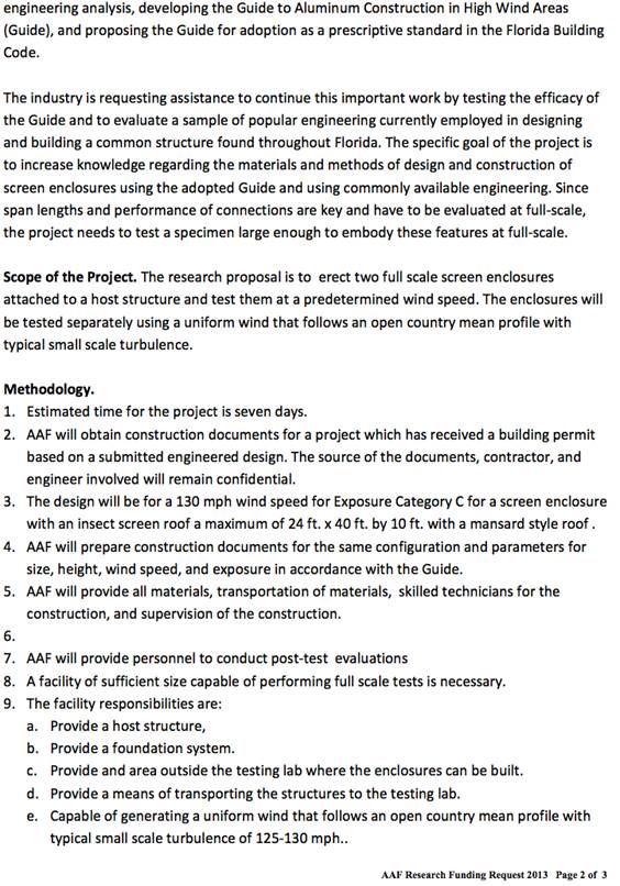
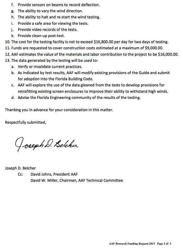
The letter from Joe Belcher on behalf of the
Aluminum Association of Florida (AAF) describes the project (see Appendix). FBC
Staff requested that we provide third-party technical input, witness testing,
and provide a final review of the report.
Dr. Sungmoon Jung, Assistant Professor of
Civil and Environmental Engineering at Florida State University, is providing
primary consultation with support from UF. Dr. Jung was selected based on his
research experience in this area. More information on this work may be found in
Schellhammer and Jung (2012) and Lewis et al. (2013).
·
Nothing to report; section reserved for final
report
- Provide consultation to AAF on the
experimental design
- Witness testing at the IBHS Research
Center
- Interpret results, determine if the
problem requires action (or not), and produce a report that explains the
results and implications for the Code
·
A report providing
technical information on the problem background, results and implications to
the Code submitted to the Program Manager by June 15, 2014
·
A breakdown of
the number of hours or partial hours, in increments of fifteen (15) minutes, of
work performed and a brief description of the work performed. The
Contractor agrees to provide any additional documentation requested by the
Department to satisfy audit requirements
An
oversight committee consisting of members of the Aluminum Association of
Florida (AAF) and the Insurance Institute for Business & Home Safety (IBHS)
was formed. FBC staff (Mo Modani) and Chair of the Structural TAC (Jim Schock)
are also participating.
During
the first meeting (January 15, 2014), Dr. Masters discussed the scope of work,
its relation to the entire scope of projects funded by the Florida Building
Commission, and facilitated introductions among the group. Joe Belcher then led
a discussion on the original proposed plan. Drs. Jung and Reinhold discussed
prior research and the IBHS facility, respectively.
The
group agreed on performing comparative experimental testing of two screen
enclosure systems. The first system will be based on signed and sealed,
site-specific plans. This “generic” system will be based on conventional design
practice, which represents the majority of designs outside of the HVHZ in
Florida. The second system will be identical to the “generic” system except
that the design will conform to requirements set forth in the 2010 AAF Guide to Aluminum Construction in
High Wind Areas.
Completed
Tasks
1.
AAF acquired 35 signed and sealed, site-specific
plans from the St. Johns County Building Department and the City of
Jacksonville. Design criteria were either 120 mph Exposure B, 130 mph Exposure C,
or 120 mph Exposure C. Ten designs with a mansard roof with approximate dimensions
of 24 ft X 40 ft X 9 ft and a 48 in rise in the roof were selected,
de-identified, and forwarded to Dr. Jung (FSU) to review.
2.
FSU selected one set for the test matrix. A
principle consideration was selecting the most representative system (outside
of the HVHZ) that is expected to show average performance. This is the ‘generic
case’
3.
AAF reviewed the selected plans and coordinated
with FSU and IBHS to resolve any ambiguities in the plans and geometric
incompatibilities with the host building
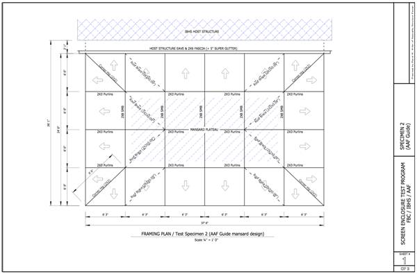
1.
AAF designed a second system similar in shape
and function to the site-specific drawings following the 2010 AAF Guide to Aluminum Construction in High Wind Areas.
Significant differences between the “generic” and the “AAF” specimens include:
·
AAF posts are all 2X4 SMB
·
AAF eave rail is 2X3 hollow with a 1X2 OB (vice
2X2 + 1X2)
·
AAF beams are 2X8 SMB vice 2X4 SMB
·
AAF purlins are all 2X3 hollow
·
AAF specimen has roof bracing as detailed
·
Some AAF purlins require backing plates (at bracing
bays)
·
AAF model uses 5” Super Gutter, while generic
uses 7”
4.
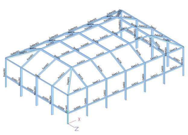
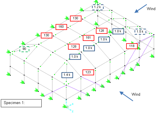
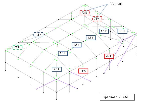
AAF and FSU performed structural analysis on the
specimens to predict the highest anticipated internal forces / stresses. Visual
Analysis 11 and SAP2000 were used, respectively. The AAF design and the structural
model is shown in Appendix B
5.
Findings were forward to IBHS to select
locations for the strain gauges. The strain gauge locations are shown in
Appendix C
Remaining
tasks
6.
Hartshorn Custom Contracting will fabricate both
specimens on identical stages provided by IBHS. A 18 ×14 × 0.013" fiberglass
mesh will be used throughout
7.
AAF will inspect the structures
8.
IBHS (Reinhold), FSU (Moon) and UF (Masters)
will instrument the structures with strain gauges based on this analysis.
Deflection measurements may also be made using a photogrammetry system owned by
UF
9.
Full-scale testing at the IBHS Research Center will
be performed on April 24 and 26
10. FSU
will analyze the data and produce a preliminary report by May 8
11. UF
and FSU will present findings to the AAF technical/engineering committees in
May
12. UF
will submit the final report to the FBC by June 15
13. UF
and FSU will present the results the FBC on June 22 or 23 (TBD by
Madani)
14. The
project will concludes on June 30
·
2010 AAF
Guide to Aluminum Construction in High Wind Areas. Available at http://www.aaof.org/resources/aaf-design-guide/aaf-guide-to-aluminum-construction-in-high-wind-areas-non-members/.
·
J.
Lewis, S. Jung and P. Mtenga (2013), Performance of screen enclosures under
repeated loading cycles, ASCE Journal of Performance of Constructed Facilities,
v 27, p 415-423
·
M.
Schellhammer and S. Jung (2012), Assessment of aluminum screen enclosure connections
subjected to strong winds, Engineering Structures, v 43, p 78-87